Note
Go to the end to download the full example code.
Solid Model#
This example shows how to create and shape a solid model.
The solid model implements an extrusion algorithm which creates
a layered solid mesh based on the shell mesh and layup definition.
This solid mesh can be further processed by ExtrusionGuide,
SnapToGeometry, and CutOffGeometry.
Import the standard library and third-party dependencies.
import pathlib
import tempfile

import pyvista
Import the PyACP dependencies.
from ansys.acp.core import (
    CADGeometry,
    CutOffGeometryOrientationType,
    EdgeSetType,
    ExtrusionGuideType,
    SnapToGeometryOrientationType,
    VirtualGeometry,
    get_directions_plotter,
    launch_acp,
)
from ansys.acp.core.extras import (
    FLAT_PLATE_SOLID_CAMERA,
    ExampleKeys,
    get_example_file,
    set_plot_theme,
)
Set the plot theme for the example. This is optional, and ensures that you get the same plot style (theme, color map, etc.) as in the online documentation.
set_plot_theme()
Load a minimal model#
tempdir = tempfile.TemporaryDirectory()
WORKING_DIR = pathlib.Path(tempdir.name)
input_file = get_example_file(ExampleKeys.MINIMAL_FLAT_PLATE, WORKING_DIR)
Launch the PyACP server and connect to it.
acp = launch_acp()
Load the model from the input file.
model = acp.import_model(input_file)
Create a simple layup#
Add more layers to the modeling ply so that it is easier to see the effects of the selection rules.
modeling_ply = model.modeling_groups["modeling_group"].modeling_plies["ply"]
modeling_ply.number_of_layers = 3
Create an initial solid model#
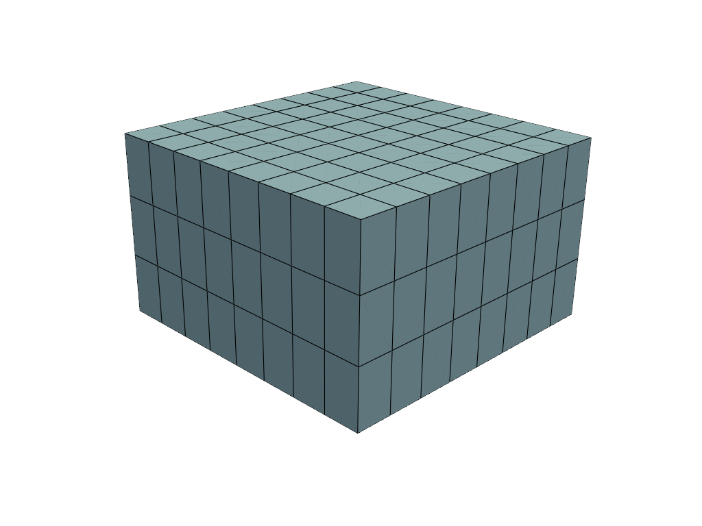
By default, the layup is extruded along the normal direction of the shell mesh.
solid_model = model.create_solid_model(
    name="Solid Model",
    element_sets=[model.element_sets["All_Elements"]],
)

model.update()


def plot_model_with_geometry(cad_geometry: CADGeometry | None, cad_geom_opacity: float = 0.1):
    """Plot solid model and geometry."""
    plotter = pyvista.Plotter()
    if cad_geometry:
        geom_mesh = cad_geometry.visualization_mesh.to_pyvista()
        plotter.add_mesh(geom_mesh, color="green", opacity=cad_geom_opacity)
        edges = geom_mesh.extract_feature_edges()
        plotter.add_mesh(edges, color="white", line_width=4)
        plotter.add_mesh(edges, color="black", line_width=2)
    plotter.add_mesh(model.solid_mesh.to_pyvista(), show_edges=True)
    plotter.camera_position = FLAT_PLATE_SOLID_CAMERA
    plotter.show()


plot_model_with_geometry(None)


def create_virtual_geometry_from_file(
    example_key: ExampleKeys,
) -> tuple[CADGeometry, VirtualGeometry]:
    """Create a CAD geometry and virtual geometry."""
    geometry_file = get_example_file(example_key, WORKING_DIR)
    geometry_obj = model.create_cad_geometry()
    geometry_obj.refresh(geometry_file)  # upload and load the geometry file
    model.update()
    virtual_geometry = model.create_virtual_geometry(
        name="thickness_virtual_geometry", cad_components=geometry_obj.root_shapes.values()
    )
    return geometry_obj, virtual_geometry
Snap the top to a geometry#
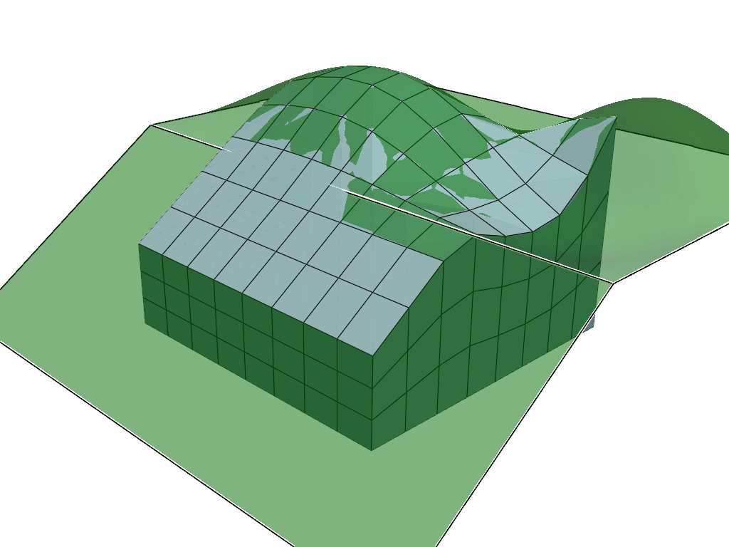
The SnapToGeometry allows to shape the bottom or top of the solid model.
First, import the geometry and then add the snap-to feature to the solid model.
snap_to_geom, snap_to_virtual_geom = create_virtual_geometry_from_file(ExampleKeys.SNAP_TO_GEOMETRY)
solid_model.create_snap_to_geometry(
    name="Snap-to Geometry",
    cad_geometry=snap_to_virtual_geom,
    orientation_type=SnapToGeometryOrientationType.TOP,
    oriented_selection_set=model.oriented_selection_sets["oss"],
)

model.update()
plot_model_with_geometry(snap_to_geom, 0.5)
Shape the walls#
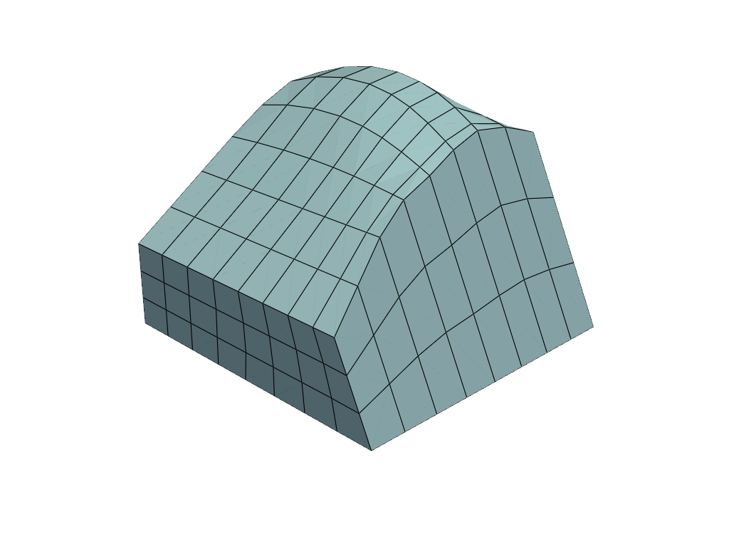
The ExtrusionGuide is used to shape the side walls of the solid model.
The feature can be defined by a direction as shown here or through a geometry.
edge_set = model.create_edge_set(
    name="Edge Set",
    edge_set_type=EdgeSetType.BY_REFERENCE,
    element_set=model.element_sets["All_Elements"],
    limit_angle=30,
    origin=(0.05, 0, 0),
)
solid_model.create_extrusion_guide(
    name="Extrusion Guide",
    edge_set=edge_set,
    extrusion_guide_type=ExtrusionGuideType.BY_DIRECTION,
    direction=(-0.5, 1, 0),
    radius=0.005,
    depth=0.6,
)
model.update()
plot_model_with_geometry(None)
Cut-off an edge#
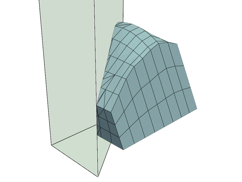
The CutOffGeometry is used to crop elements from the solid model.
cut_off_cad_geom, cut_off_virtual_geom = create_virtual_geometry_from_file(
    ExampleKeys.CUT_OFF_GEOMETRY_SOLID_MODEL
)
solid_model.create_cut_off_geometry(
    name="Cut-off Geometry",
    cad_geometry=cut_off_virtual_geom,
    orientation_type=CutOffGeometryOrientationType.UP,
)

model.update()
plot_model_with_geometry(cut_off_cad_geom)
Plot results on the solid mesh#
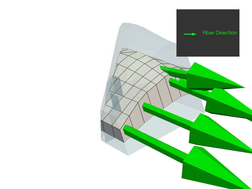
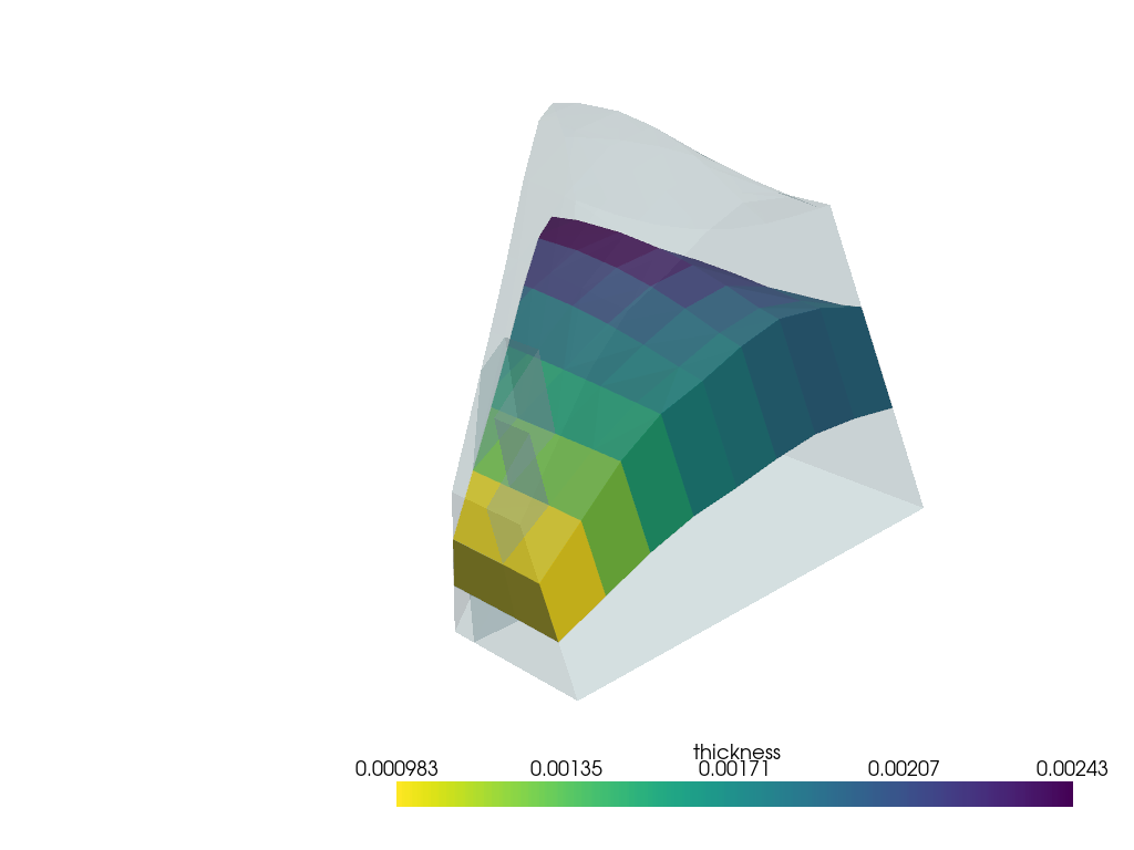
The plotting capabilities also support the visualization of ply-wise results, such as directions or thicknesses as shown here.
Get the analysis ply of interest
ap = solid_model.analysis_plies["P2L1__ply"]
Plot fiber directions#
direction_plotter = get_directions_plotter(
    model=model,
    mesh=ap.solid_mesh,
    components=[
        ap.elemental_data.fiber_direction,
    ],
    length_factor=10.0,
    culling_factor=10,
)
direction_plotter.add_mesh(model.solid_mesh.to_pyvista(), opacity=0.2, show_edges=False)
direction_plotter.camera_position = FLAT_PLATE_SOLID_CAMERA
direction_plotter.show()
Plot thicknesses#
thickness_data = ap.elemental_data.thickness
thickness_pyvista_mesh = thickness_data.get_pyvista_mesh(mesh=ap.solid_mesh)  # type: ignore
plotter = pyvista.Plotter()
plotter.add_mesh(thickness_pyvista_mesh)
plotter.add_mesh(model.solid_mesh.to_pyvista(), opacity=0.2, show_edges=False)
plotter.camera_position = FLAT_PLATE_SOLID_CAMERA
plotter.show()
Total running time of the script: (0 minutes 6.836 seconds)

